In 1824, a 28-year-old French engineer named Sadi Carnot published a slim pamphlet entitled Réflexions sur la puissance motrice du feu — Reflections on the Motive Power of Fire. In those 65 pages, Carnot laid the theoretical foundation for all of thermodynamics, and in doing so established something that every engineer working with combustion systems still lives with today: there is a fundamental, inescapable upper limit to how efficiently heat can be converted to work.
The Carnot Limit and Why It Matters for Furnaces
Carnot's insight was that any heat engine operating between a hot reservoir at temperature Th and a cold reservoir at temperature Tc (both in Kelvin) can achieve at most an efficiency of:
ηCarnot = 1 − Tc / Th
For a gas turbine combustion chamber operating at a flame temperature of 1800 K (approximately 1527°C) and exhausting to the atmosphere at 300 K (27°C), the theoretical Carnot efficiency is 1 − (300/1800) = 83.3%. This sounds impressive — but it is strictly theoretical, available only to an idealised reversible engine operating infinitely slowly. Real systems must operate at finite speed, with real heat transfer resistances, real friction losses, and real irreversibilities at every step.
For an industrial boiler or furnace — where the goal is not primarily to produce shaft work but to transfer heat to a process fluid or working environment — the Carnot framework still provides a useful boundary, but the relevant efficiency metric is different: it is the fraction of the fuel's chemical energy that ends up usefully transferred to the desired heat load, rather than being lost up the flue, dissipated through the boiler shell, or wasted as unburned fuel.
"In a real boiler, every degree of excess flue gas temperature represents money and carbon going up the chimney. Closing the gap between theoretical and actual efficiency is one of the central challenges of modern combustion engineering."— M. Kohlberg, Technical Contributor, Furnace-Cleaning Review
The Three Major Combustion Efficiency Losses
In any real combustion system, the gap between the theoretical energy content of the fuel and the energy usefully delivered to the load can be attributed to three broad categories of loss.
1. Dry flue gas losses. Hot combustion products leaving the furnace at temperatures significantly above ambient carry energy that has been irreversibly lost to the process. This is typically the largest single loss in well-maintained systems. A gas boiler operating with a flue gas exit temperature of 200°C will lose approximately 5–8% of input energy in dry flue gas. Modern condensing boilers, which cool the flue gas below the dew point of water vapour and recover the latent heat of condensation, can reduce flue gas exit temperatures to 40–60°C — cutting this loss to 1–2% and achieving gross efficiencies of 95–98% against the lower heating value (LHV) of the fuel.
2. Unburned combustibles. If combustion is incomplete — whether through insufficient oxygen, poor mixing, inadequate temperature, or short residence time — some of the chemical energy in the fuel leaves the system as unburned hydrocarbons, carbon monoxide, or unburned particulate carbon (soot). In a properly tuned modern gas burner, these losses are below 0.1%. In a poorly maintained oil burner with a clogged nozzle or incorrect air-to-fuel ratio, they can reach 5–10% and are visible as smoke and soot emissions.
3. Radiation and convection losses from the boiler shell. Even well-insulated combustion equipment loses some heat through its outer surfaces to the surrounding environment. In large industrial boilers, this is typically 0.5–2% of input energy; in small domestic appliances it can be higher as a percentage but lower in absolute terms.
The sum of these losses determines the efficiency gap. In a well-designed modern condensing boiler operating on natural gas, the total loss can be held below 5%, implying an overall efficiency above 95% (LHV basis). In an older non-condensing boiler from the 1970s, the same losses might total 25–30%, representing a massive waste of fuel that the Netherlands' national energy efficiency programme (the Energieakkoord and its successors) has systematically worked to eliminate through mandatory replacement programmes and efficiency labelling.
Combustion Stoichiometry and Excess Air
At the heart of combustion efficiency management is the control of air-to-fuel ratio. Complete combustion of methane (CH₄) requires exactly two moles of oxygen per mole of fuel — the stoichiometric ratio. In practice, furnaces always operate with some excess air to ensure complete combustion even with imperfect mixing: a 10% excess air supply (equivalence ratio λ = 1.1) is typical for a well-controlled gas burner. This excess air dilutes the combustion products, reducing the flame temperature and increasing the volume of flue gas to be cooled — both of which increase dry flue gas losses. Conversely, insufficient air (λ < 1.0) results in fuel-rich combustion, with the penalties of CO formation, soot production, and significant unburned fuel loss.
Modern gas burners are fitted with oxygen sensors (lambda probes or zirconia sensors) in the flue gas stream that continuously monitor the oxygen concentration and feed back to an electronic control system that trims the air-to-fuel ratio in real time. The best systems maintain excess air levels of 5–10% across the full load range, representing a significant efficiency improvement over earlier fixed-air systems that were necessarily set conservatively to provide adequate combustion margins under all operating conditions.
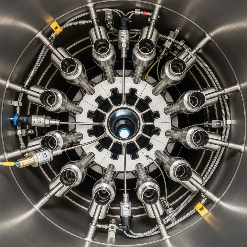
Heat Transfer Mechanisms in Industrial Combustion Chambers
Three heat transfer mechanisms operate simultaneously within an industrial combustion chamber, each with different characteristics and sensitivities to operating conditions.
Thermal radiation dominates at high temperatures and accounts for 60–80% of heat transfer in the primary combustion zone of large industrial furnaces. Radiation from soot particles (luminous radiation), from tri-atomic gas species (CO₂ and H₂O, which emit and absorb strongly at specific infrared wavelengths), and from the high-temperature furnace walls all contribute. The Stefan-Boltzmann law (q ∝ T⁴) means that radiative heat transfer is extremely sensitive to temperature: halving the absolute temperature reduces radiation by a factor of 16. This is why modern furnaces maintain very high primary zone temperatures even at the cost of some NOₓ emissions — the radiative heat transfer gain more than compensates for the increased nitrogen oxide formation, which is managed through downstream flue gas treatment.
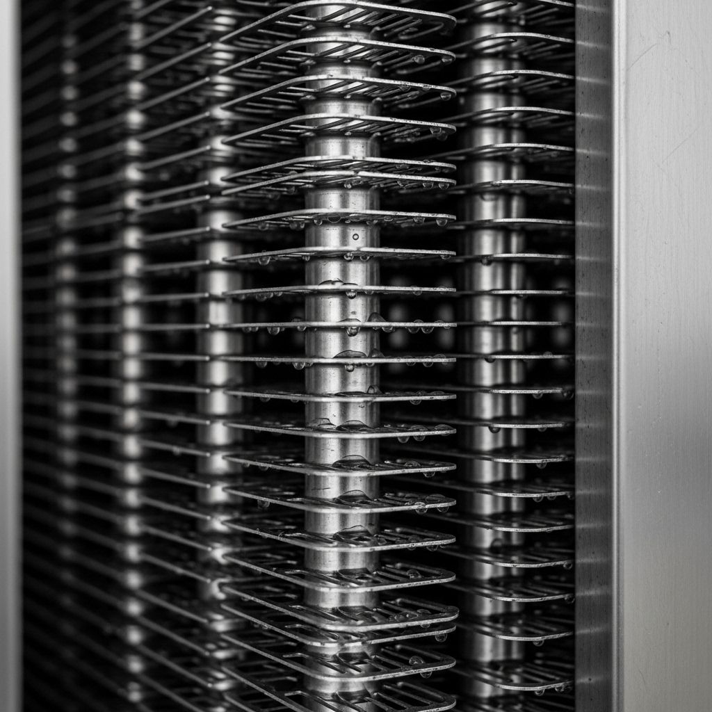
Convection transfers heat from the hot combustion gases to the heat exchanger surfaces as they flow through the furnace and flue passes. The convective heat transfer coefficient depends on the gas velocity, the tube geometry, and the gas properties. Modern heat exchanger design uses turbulence-enhancing geometries — spiral tubes, corrugated surfaces, castellated fins — to maximise the convective coefficient without excessive pressure drop penalties.
Conduction through the heat exchanger wall itself is generally not the limiting step in modern metallic heat exchangers (where wall thermal resistance is negligible compared to the gas-side and water-side film resistances), but it becomes important in the presence of fouling deposits. A 1 mm layer of soot on a heat exchanger surface — negligible in visual terms — adds a thermal resistance equivalent to approximately 10 mm of steel. This is why regular cleaning of heat exchanger surfaces is not merely a maintenance formality but a fundamental thermodynamic necessity: soot fouling directly increases flue gas temperature, increases fuel consumption, and reduces the life of the exchanger by raising its surface temperature.
Case Study: The Dutch Industrial Heat Sector
The Netherlands has one of Europe's highest energy intensities in the industrial sector, driven by the large chemical, food processing, and refinery industries concentrated in the Rotterdam port area (Rijnmond) and the North Sea Canal zone. Industrial heat demand — primarily as steam and hot water in the range 100–400°C — accounts for approximately 40% of total Dutch industrial energy consumption.
Following the energy crises of the 1970s and the subsequent introduction of EU emissions legislation, Dutch industry has been at the forefront of combustion efficiency improvement. The Rotterdam refinery complex has implemented heat integration schemes (pinch analysis) that recover waste heat from high-temperature process streams to satisfy lower-temperature process demands, dramatically reducing the total combustion load required per unit of product. The combined heat and power (WKK — warmtekrachtkoppeling) sector has expanded substantially, with plants at the Shell Pernis refinery and the AkzoNobel Delfzijl chemical complex achieving overall primary energy efficiencies above 85% by simultaneous generation of electricity and process steam.
The challenge going forward is the decarbonisation of industrial heat. Unlike residential heating — where electrification via heat pumps is technically straightforward — industrial processes requiring temperatures above 200°C cannot easily be served by standard heat pumps. Research at Delft University of Technology (TU Delft) and the Netherlands Organisation for Applied Scientific Research (TNO) is exploring combinations of high-temperature heat pumps, electric resistance heating, hydrogen combustion, and novel thermal storage technologies for the post-fossil industrial heat supply.
Looking Forward: Hydrogen Combustion and Its Thermodynamic Implications
The Dutch government's hydrogen strategy envisages substantial volumes of green hydrogen (produced by electrolysis using renewable electricity) replacing natural gas in industrial combustion applications from the early 2030s. Hydrogen combustion presents a different set of thermodynamic and engineering challenges compared to methane combustion: the adiabatic flame temperature of hydrogen–air is slightly higher (approximately 2100°C versus 1950°C for methane), the laminar burning velocity is approximately seven times higher, and the combustion products contain no CO₂ but substantially more water vapour.
The higher water vapour content has a direct efficiency implication: the latent heat of condensation of water in the flue gas is larger for hydrogen combustion, making the efficiency gain from condensing operation proportionally greater. However, the higher flame temperature increases NOₓ formation through the thermal NOₓ pathway (Zeldovich mechanism), requiring careful burner design to avoid exceeding EU Industrial Emissions Directive limits. Flameless oxidation (FLOX) burners, which operate by recirculating hot flue gas into the combustion zone and reducing peak temperatures while maintaining complete combustion, are among the most promising approaches for low-NOₓ hydrogen combustion in industrial furnaces.
The thermodynamics of combustion, then, is not a solved problem consigned to textbooks. It is a live field of engineering research and industrial practice, with genuine implications for the Netherlands' ability to meet its 2030 and 2050 climate obligations. Carnot's fundamental insight — that the conversion of heat to work is bounded by the ratio of absolute temperatures — remains as relevant today as it was in 1824. The task of the combustion engineer is to close the gap between that theoretical limit and the imperfect reality of real furnaces, real fuels, and real constraints.
Key References
- Carnot, S. (1824). Réflexions sur la puissance motrice du feu et sur les machines propres à développer cette puissance. Bachelier, Paris.
- Turns, S.R. (2011). An Introduction to Combustion: Concepts and Applications, 3rd edn. McGraw-Hill.
- TNO (2023). Industrial Heat Decarbonisation in the Netherlands: Technology Readiness and Deployment Pathways. Netherlands Organisation for Applied Scientific Research, Delft.
- Energieonderzoek Centrum Nederland (ECN/TNO). (2022). Rendementen en CO₂-emissiefactoren van energieopwekking in Nederland. Petten: ECN-TNO.
- Baukal, C.E. (ed.) (2000). Heat Transfer in Industrial Combustion. CRC Press, Boca Raton.